News
Contact Us
Phone : +86 0531-85908792
Email:Admin:zrsuns@outlook.com Sales:sales@rubylasercutting.com
Skype: ZRsunslaser
Q Q: 2407603284
Mobile :+86-13295411923

Industry News
Common faults of laser power supply
- source:Jinan Ruby Laser Technology Co., Ltd
- author:
- time:2021-01-03 01:06:25
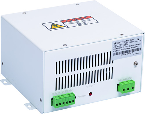
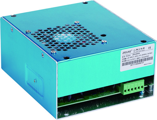
It can be expected that there will be some failures in the end, but what about the DC excitation laser power supply? Why is the failure of this component inevitable? Is it because of cheap buildings, or more? In this paper, we will explore the potential failure modes of laser power supply.
First of all, we must understand the purpose of the power supply and how it works.
DC excited glass laser tubes need a very high voltage at a moderate low current to maintain arc in inert gas vacuum.
When we say high voltage, what we mean is true. The range we are talking about is 28-50 kV, that is 50000 v.
Obviously, the power supply voltage you feed into the machine must be converted to that obscene voltage in some way.
This happens in multiple stages.
High voltage safety
If possible, work on an unpowered circuit.
Be very careful around the live 50 / 60 Hz current, as it hardly needs to hurt the current. Your power may kill you!
Limit the current and energy to the lowest possible value. Many interesting experiments can be carried out under low storage power and low current of several Ma or even microampere. Make it a habit to ask yourself if you really need this kind of current or energy.
Keep a distance from the live high voltage circuit. As the high voltage will break through the air and connect you to the circuit, please put the high voltage circuit in the enclosure and behind the roadblock during operation.
Ensure that the test and cabinet are properly grounded. Before carrying out circuit maintenance, please be very careful to ensure that the circuit is powered off and grounded. Know when and how to finally enter the grounding path of the circuit, and take appropriate protective measures to eliminate this situation.
Never work alone, always have a partner who understands your equipment and the risks and hazards involved. In this way, you have another pair of safe eyes, and someone can turn off the power and ask for help in case of injury.
Disclaimers
The author does not make any statement as to the completeness or accuracy of the information contained herein, nor does he make any statement as to the incompleteness, incorrect information, misunderstanding of direction, misuse of circuits and information or otherwise. Even if a specific purpose is specified in the text, the author, contributor and owner explicitly deny any implied intent
Guarantee and fitness for any particular purpose.
Phase I - rectification
AC voltage must be converted to DC voltage, which requires the use of bridge rectifier circuit to convert the sine wave of AC signal into a positive voltage, by using multiple diodes to reverse the negative part of the sine wave. Wheatstone bridge configuration.
Stage 2 - conditioning
Although DC rectifier voltage is far from suitable for this application, the signal must be processed to smooth the high and low levels into acceptable signals. The rectifier voltage is smoothed by two large 820uf capacitors.
Phase 3 - switching
Now the smooth DC voltage must be modulated, which is the way the output power changes. The regulated voltage from stage 2 is fed into a pair of fast switching power transistors (MOSFETs), which are similar to relays in principle, but with some very important differences. At this stage
The output is called root mean square voltage (RMS).
Turn on and turn off voltage, turn on and turn off time is called duty cycle. Once the duty cycle is averaged over time, it can be regarded as the average output voltage. Although it is always 100% of the input voltage, it will modulate over time.
Stage 4 - voltage conversion
If 220 V input or 55 V is 110 V input, the DC voltage near 99 V must be converted to very high voltage. This occurs inside a pair of high voltage flyback transformers. Flyback transformer is a large inductor that can store energy as well as primary and secondary windings.
The primary winding is connected to the DC voltage through a power MOSFET in the conduction region. The inductor stores the voltage. Once the MOSFET disconnects the primary winding from the DC voltage, the energy is transferred to the secondary winding.
The flyback transformer increases the voltage in stages.
- Previous:没有了
- Next:What is the practicability of laser power supply?
News
-
2023-07-13 17:08:52
How precautions...
-
2023-06-08 19:39:55
How to better u...
-
2023-05-15 10:40:31
How to apply ce...
-
2023-04-24 16:57:25
Leading laser p...
-
2023-04-11 16:06:33
Zhonggu Lianchu...
-
2021-01-03 01:08:29
What is the pra...


 2407603284
  ZRsunslaser